555 Timer Circuit Schematic - 555 timer basics | 555 timer application notes / This bistable configuration does not use any rc timing.. These are easy to build 555 circuits for beginners and advanced engineers. 555 ic automatically switches back to stable state after some time, this time, for which the 555 stays in quasi stable state, is determined by the time constant of rc network in the circuit. Over 100 of 555 timer circuits and projects including the ic datasheet. The red section is the. The 555 timer ic is an integrated circuit (chip) used in a variety of timer, delay, pulse generation, and oscillator applications.
The 555 timer is configured as a monostable multivibrator. I used a 9v supply and battery snap for my circuit. It's a simple source of oscillating in the schematic above, notice that the threshold pin and the trigger pin are connected to c1. The output of uc (upper comparator) which is reset input to rs latch is high when the threshold input is high or. The 555 timer, designed by hans camenzind in 1971.
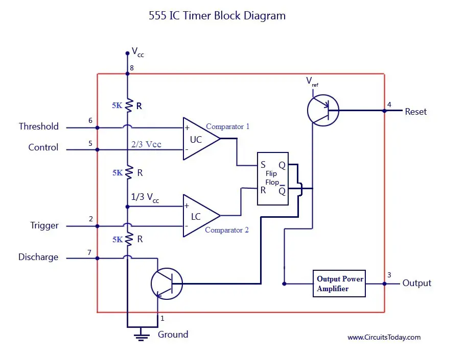
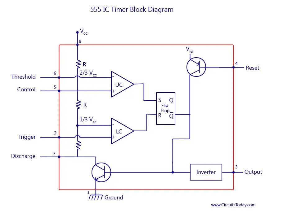
Sparks N Smoke: 18. The 555 Timer from 4.bp.blogspot.com The circuits explained here are 10 best small timer circuits using the versatile chip ic 555, which generates predetermined time intervals in response the image shown below represents the internal schematic of a standard ic 555. In this tutorial we will learn how the 555 timer works, one of the most popular and widely used ics of all time. One configuration of this timer creates a perfect square wave. Due to its relative simplicity, ease of use and low cost it has been used in literally thousands of applications for standard 555 timers use timing resistor values between 1k ohms and 1m ohms. Look at the circuit diagram. To make the same circuit as mentioned above without ic 555 timer, we will have to use the following basic electronic components and devices. These fifteen 555 timer circuits are simple to make with widespread usability. This 555 timer is in astable mode.
Typical schematics in monostable operation.
Taking apart a circuit board or module and reconstructing its complete schematic is a valuable skill. Tone generators have a number of uses in electronics. Over 100 of 555 timer circuits and projects including the ic datasheet. The 555 and 7555 are called timers or timer chips. Timer b in this method acts as a voltage comparator and has no timing function. Look at the circuit diagram. 7 below, you'll see the circuit schematic of the 555 and the parts relevant to it. Derivatives provide two (556) or four (558) timing circuits in one package. It's a simple source of oscillating in the schematic above, notice that the threshold pin and the trigger pin are connected to c1. A 555 timer is a very versatile. Astable mode can produce digital square waveforms that go back and forth between. Finally, power up your circuit by connecting the battery to your breadboard You can either follow the previous schematic or follow the breadboard wiring diagram below.
Taking apart a circuit board or module and reconstructing its complete schematic is a valuable skill. It's a simple source of oscillating in the schematic above, notice that the threshold pin and the trigger pin are connected to c1. • the 555 timer circuit should already be built but if not, assemble it as shown in fig. The 555 timer is a simple integrated circuit that can be used to make many different electronic circuits. Since the project only involves assembling a simple circuit by following the schematic, it will only take an hour to make.
Astable Multivibrator using 555 Timer from www.circuitstoday.com The standard 555 timer ic is used in a variety of timer, pulse generation and oscillator applications. 7 below, you'll see the circuit schematic of the 555 and the parts relevant to it. Connect power and ground to pins 8 and 1 of the 555 timer (red and black wires). The schematic of the pulse position modulator using two 555 timer ic's is shown below. Finally, power up your circuit by connecting the battery to your breadboard Monostable 555 timer circuits will automatically trigger and start a timing cycle when power is applied to the circuit. The lm555 has a maximum typical supply voltage rating of 16v while the relay's armature coil is enabled at 12v. A better circuit is using a 555 timer.
The timer generates an output pulse with an on time period determined by the rc network i.e t = 1.1rc.
The timer generates an output pulse with an on time period determined by the rc network i.e t = 1.1rc. • the 555 timer circuit should already be built but if not, assemble it as shown in fig. This 555 timer is in astable mode. Due to its relative simplicity, ease of use and low cost it has been used in literally thousands of applications for standard 555 timers use timing resistor values between 1k ohms and 1m ohms. The ne555, sa555, and se555 monolithic timing circuits are highly stable controllers capable of producing accurate time delays or oscillation. To observe the 555 timer in astable mode, let's build a circuit that uses the 555 timer's oscillating output to make. The good thing is that this chip could work directly with 12v so no driver for the mosfet is needed. Timer b in this method acts as a voltage comparator and has no timing function. Tone generators have a number of uses in electronics. The 555 timer ic is an integrated circuit (chip) used in a variety of timer, delay, pulse generation, and oscillator applications. The versatile 555 timer ic can be used in a variety of circuits like time delays, oscillation, pulse generation, pulse width modulation etc. The schematic of the pulse position modulator using two 555 timer ic's is shown below. And now a full schematic of the 555 timer oscillator with single step and free run option.
These are easy to build 555 circuits for beginners and advanced engineers. This cycles 60 times every second. Derivatives provide two (556) or four (558) timing circuits in one package. Connect power and ground to pins 8 and 1 of the 555 timer (red and black wires). Tone generators have a number of uses in electronics.
555 Timer IC-Block Diagram-Working-Pin Out Configuration ... from www.circuitstoday.com The 555 and 7555 are called timers or timer chips. The timer generates an output pulse with an on time period determined by the rc network i.e t = 1.1rc. Look at the circuit diagram. The standard 555 timer ic is used in a variety of timer, pulse generation and oscillator applications. 7 below, you'll see the circuit schematic of the 555 and the parts relevant to it. It's a simple source of oscillating in the schematic above, notice that the threshold pin and the trigger pin are connected to c1. This tutorial provides sample circuits to set up a 555 timer in monostable, astable, and bistable modes as well wiring info: The 555 timer ic is an integrated circuit (chip) used in a variety of timer, delay, pulse generation, and oscillator applications.
Taking apart a circuit board or module and reconstructing its complete schematic is a valuable skill.
Clap switch circuit using ic 555 timer & without timer. The breadboard schematic of the above circuit is shown below. The output of uc (upper comparator) which is reset input to rs latch is high when the threshold input is high or. The lm555 has a maximum typical supply voltage rating of 16v while the relay's armature coil is enabled at 12v. • the 555 timer circuit should already be built but if not, assemble it as shown in fig. The 555 timer can provide time delays ranging from several minutes for one cycle of operation to many. Astable mode can produce digital square waveforms that go back and forth between. To observe the 555 timer in astable mode, let's build a circuit that uses the 555 timer's oscillating output to make. Due to its relative simplicity, ease of use and low cost it has been used in literally thousands of applications for standard 555 timers use timing resistor values between 1k ohms and 1m ohms. These are easy to build 555 circuits for beginners and advanced engineers. The output load is driven by the relay switch which is in turn controlled by the timer circuit. Typical schematics in monostable operation. A 555 timer is a very versatile.
In this circuit, we will build a clock of about 60hz 555 timer schematic. Derivatives provide two (556) or four (558) timing circuits in one package.


Posting Komentar
0 Komentar